

LED matrix displays aren’t just for holiday decorations—they’re for sending messages, the hacker way.
A few years ago, I found myself staring at a blinking 8×8 LED matrix display, utterly convinced it was just a flashy Christmas prop. Fast forward to today, and I’m using the same kind of display—powered by an ESP32 running MicroPython—to broadcast real-time system alerts, scrolling messages, and even OSINT reconnaissance data during CTF sessions.
The turning point? Realizing that LED matrix displays weren’t just decorative—they were programmable canvases for ethical hackers, educators, and FOSS builders who value low-cost, high-impact tech.
If you’ve got an ESP32, a bit of curiosity, and a preference for tools that respect your freedom, you’re about to unlock something fun and functional. Let’s walk through the entire process, step-by-step.
👉 Read on to light up your own LED matrix display using nothing but MicroPython and open-source tools.
What are LED Matrix Displays?

An LED matrix is a grid of LEDs arranged in rows and columns, with each LED being individually controllable to create images, characters, or patterns. LED matrices are commonly available in sizes like 8×8, 16×16, or larger. With the right setup, you can use these matrices to display a variety of dynamic content such as scrolling text, animations, and even real-time data. The ESP32 is well-suited for controlling LED matrix displays due to its fast processing speed and multiple GPIO pins.
Micropython MAX7219 LED Matrix Driver Documentation
What is SPI (Serial Peripheral Interface)?
Before diving into controlling the LED matrix, it’s important to understand how the ESP32 communicates with these displays. The Serial Peripheral Interface (SPI) is a high-speed communication protocol used to transfer data between a microcontroller (like the ESP32) and peripheral devices such as sensors, displays, and memory modules.
Key Characteristics of SPI:
- Full-Duplex: SPI allows data to be sent and received simultaneously, enabling faster communication than some other protocols.
- Four Wires: SPI uses four main signal lines for communication:
- MOSI (Master Out, Slave In): This is the data line from the master to the slave.
- MISO (Master In, Slave Out): This is the data line from the slave to the master.
- SCK (Serial Clock): This is the clock line controlled by the master to synchronize data transmission.
- SS/CS (Slave Select/Chip Select): This is a control line used by the master to select which slave device it wants to communicate with.
SPI is widely used because it is fast, flexible, and simple to implement in hardware, and it supports a wide range of devices. The ESP32 has multiple SPI peripherals, making it ideal for high-speed communication with devices like LED matrix displays.
What is the MAX7219 Chip?

The MAX7219 is a serially interfaced LED driver chip used to control 7-segment displays, 8×8 LED matrices, and bar graph LEDs. It simplifies controlling a large number of LEDs using just a few pins on the microcontroller. The MAX7219 handles tasks like multiplexing and current regulation, which makes it perfect for driving LED matrices.
Check the MAX7219 Datasheet here.
Key Features of the MAX7219:
- Simplifies LED Control: It reduces the number of GPIO pins required to control multiple LEDs or a display matrix.
- Multiplexing: The MAX7219 automatically handles the multiplexing of LEDs, turning on rows and columns at the right times to make all LEDs appear illuminated simultaneously.
- Daisy-Chaining: Multiple MAX7219 chips can be chained together to control larger displays, like arrays of 8×8 matrices, using a single SPI connection.
- Adjustable Brightness: You can control the brightness of the LEDs through a built-in register.
- Integrated Functions: The chip supports features like display shutdown, test mode, and decoding of 7-segment data, making it highly efficient for LED matrix applications.
Setting Up the Hardware
Before we get into the coding, you’ll need a few key components:
- ESP32 Development Board: This microcontroller will control the LED matrix and can be programmed with MicroPython.
- LED Matrix Display: A typical choice for small projects is the 8×8 LED matrix, but you can opt for larger ones if you need more visual space.
- MAX7219 Driver Chip: This chip allows easy communication with the ESP32 and manages the LED matrix.
- Wiring: Jumper wires to connect the ESP32 to the matrix.
- Power Supply: Ensure that both the ESP32 and LED matrix are powered appropriately.
Wiring the ESP32 to the LED Matrix
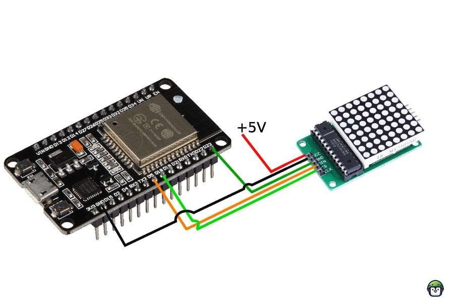
The simplest way to connect the ESP32 to an LED matrix is through a driver IC like the MAX7219. This IC allows you to control the entire matrix with fewer GPIO pins. Here’s how to wire your ESP32 to the MAX7219 and the LED matrix:
| MAX7219 Pin | Connection |
|---|---|
| GND | GND (ESP32 and power supply) |
| VCC | 5V (from power supply) |
| DIN | GPIO 23 (SPI MOSI) |
| CS | GPIO 5 (SPI SS) |
| CLK | GPIO 18 (SPI SCK) |
Important Notes
- Common Ground: Ensure the GND of the power supply, MAX7219, and ESP32 are connected for proper operation.
- External Power: Use an external 5V power source if driving multiple matrices to avoid overloading the ESP32’s power regulator.
· · ─ ·𖥸· ─ · ·
Programming the ESP32 with MicroPython
Now that the ESP32 is set up with MicroPython and connected to the LED matrix, it’s time to write some code. In MicroPython, we’ll use the machine module to control the GPIO pins and the max7219 library to interface with the LED matrix.
You’ll first need to install the max7219 library, which simplifies the process of controlling the LED matrix.
Here’s a basic example of how to control an 8×8 LED matrix using MicroPython:
import max7219
from machine import Pin, SPI
from time import sleep

# Configure SPI
spi = SPI(2, baudrate=10000000, sck=Pin(18), mosi=Pin(23))
ss = Pin(5, Pin.OUT)

def display_text():
    display = max7219.Matrix8x8(spi, ss, 1)
    display.fill(0)  # Clear the display
    display.text('0123456789', 0, 0, 1)  # Display text
    display.brightness(10)
    display.show()
    sleep(1)

while True:
    display_text()
Code Breakdown
- SPI Configuration:
SPI(2, baudrate=10000000, sck=Pin(18), mosi=Pin(23)): Sets up hardware SPI on the ESP32 with GPIO 18 as SCK and GPIO 23 as MOSI.ss = Pin(5, Pin.OUT): Configures GPIO 5 as the Chip Select (CS) pin.
- Display Initialization:
max7219.Matrix8x8(spi, ss, 1): Initializes the LED matrix with SPI and CS.
- Controlling LEDs:
display.fill(0): Clears the display.display.text('0123456789', 0, 0, 1): Writes text to the matrix.display.brightness(10): Sets the brightness level.display.show(): Updates the matrix with the new data.
Troubleshooting Tips
- Erratic Behavior: Ensure the GND of the power supply and ESP32 are connected. Without a shared ground, communication may fail.
- Dim LEDs or Flickering: Use a stable 5V power source, especially for multiple matrices.
- Incorrect Pin Assignments: Double-check wiring against the table above.
· · ─ ·𖥸· ─ · ·
Expanding Your Projects
Once you’re comfortable with controlling a basic LED matrix using MicroPython, you can explore more advanced projects:
- Scrolling Text: Use the
textmethod in the library to scroll messages across the display. - Animations: Display simple animations by manipulating pixel values at high speeds.
- Multiple LED Matrices: Chain multiple matrices together and expand your display area.
- Wi-Fi Integration: Use the ESP32’s Wi-Fi to display real-time data like weather reports or stock prices.
Resources:
- MicroPython max7219 cascadable 8×8 LED matrix driver (WORKING 100%)
- Pins and GPIO
- sleep
- SPI (hardware)
· · ─ ·𖥸· ─ · ·
From Flashy to Functional: Why LED Matrix Displays Deserve a Spot in Your Toolkit
We’ve gone from plugging in wires to scrolling custom text—proving that LED matrix displays paired with ESP32 aren’t just eye-catching; they’re practical tools for ethical hacking, real-time alerts, or even public-facing FOSS advocacy projects.
This guide walked you through the essentials, but it’s just the beginning. Whether you’re building for fun, education, or activism, there’s a whole world of MicroPython-powered displays waiting to be explored.
👉 Want more guides like this—built for curious hackers and FOSS-minded makers?
Subscribe to DevDigest and get hands-on tutorials, open-source tools, and practical hacking workflows in your inbox every week.
Leave a Reply