

My ESP32 potentiometer kept spiking—until I grounded it like a stubborn teenager.
The first time I wired up an ESP32 potentiometer, I was convinced the chip hated me. Every flick of the knob sent values jumping like a nervous intern in a live demo. I checked the code, rewired the pins, even swapped out the potentiometer. Still jittery. Turns out, I’d overlooked something painfully basic: proper grounding. One simple adjustment—tying GND where it actually mattered—transformed chaos into clean, stable analog input.
This isn’t just a tutorial; it’s a lesson in humility, troubleshooting, and the little hardware quirks that don’t show up in datasheets. If you’re a student, a tinkerer, or a FOSS dev who’d rather spend more time coding than debugging your breadboard, this one’s for you. Let’s walk through how to wire and read a potentiometer on ESP32 without the drama.
Scroll on to finally get smooth, reliable analog readings—FOSS style.

Understanding ADC on the ESP32
The ESP32 features built-in ADC (Analog-to-Digital Converter) modules, which allow it to interpret analog signals by converting them into digital values. ADCs work by sampling the voltage level of an analog input and assigning it a numerical value, typically within a predefined range. The ESP32’s ADC range is 0–4095 for 12-bit resolution.
ADC Applications
ADC is crucial in scenarios where sensors output analog signals, such as:
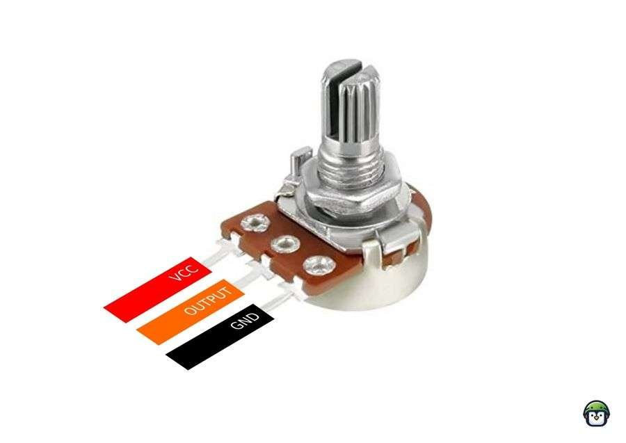
- Potentiometers: Measure resistance changes.
- Light Sensors (e.g., LDRs): Detect light intensity.
- Temperature Sensors (e.g., thermistors): Read temperature variations.
- Gas Sensors: Detect gas concentrations.
- Flex Sensors: Measure bending or pressure.
- Force-Sensitive Resistors (FSRs): Detect applied pressure.
Components and Setup
- ESP32 board
- Potentiometer
- Connecting wires
- Breadboard
Wiring Diagram
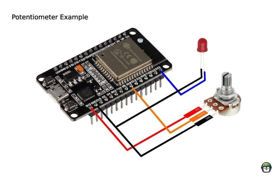
- Connect the potentiometer’s middle pin to ESP32’s ADC pin (e.g., GPIO18).
- Attach one outer pin to the 3.3V power supply.
- Attach the other outer pin to GND.
Here is a table based on the code provided, detailing the pinout for the potentiometer and LED setup:
| Component | ESP32 Pin | Description |
|---|---|---|
| Potentiometer | GPIO18 | ADC pin to read the analog signal (middle pin) |
| Potentiometer | 3.3V | Power supply (one outer pin) |
| Potentiometer | GND | Ground (other outer pin) |
| LED (PWM output) | GPIO23 | Controls LED brightness via PWM |
· · ─ ·𖥸· ─ · ·
Reading Analog Values with MicroPython
Below is the code for ESP32 Potentiometer Reading, which also calculates the voltage and controls an LED’s brightness via PWM:
from time import sleep_ms
from machine import Pin, ADC, PWM

# Setup ADC and LED
pot = ADC(Pin(18))
pot.atten(ADC.ATTN_11DB)  # Full voltage range (0-3.3V)
led = PWM(Pin(23), freq=5000)

while True:
    pot_value = pot.read()  # Read raw ADC value
    voltage = pot_value * (3.3 / 4095)  # Convert ADC to voltage
    dc = int(0.24 * pot_value)  # Calculate duty cycle

    led.duty(dc)  # Set LED brightness
    print(f"Raw Value: {pot_value}, Voltage: {voltage:.2f}V, Duty Cycle: {dc}")
    sleep_ms(50)
· · ─ ·𖥸· ─ · ·
Decoding the Math Behind the Code
Voltage Conversion Formula
The formula for voltage conversion is:
- Raw ADC Value: Output from the ADC module.
- Reference Voltage: Typically 3.3V for the ESP32.
- Resolution: 12-bit ADC results in 4095 steps (2ⁱ² – 1).
For a raw ADC value of 2048, the voltage would be:
Duty Cycle Formula
The LED’s brightness is controlled using a PWM duty cycle calculated as:
The multiplier “0.24” ensures that the duty cycle remains within the allowable PWM range (0-1023 for the ESP32). Without scaling, raw ADC values (up to 4095) would exceed the PWM range, causing incorrect behavior.
Basically the duty cycle is is 24% of the POT value.
· · ─ ·𖥸· ─ · ·
Practical Applications
This setup demonstrates how ESP32 Potentiometer Reading can be used to:
- Adjust LED brightness.
- Control motor speeds.
- Create user-friendly input devices like sliders.
· · ─ ·𖥸· ─ · ·
Conclusion: Don’t Let a Loose Ground Ruin Your Reads
We’ve covered the wiring, the read logic, and the real-life pitfalls of working with an ESP32 potentiometer—especially the kind that make your values spike like a broken lie detector. At the heart of it all? A grounding issue so subtle it’s almost poetic.
When your hardware setup starts acting weird, don’t just reach for another sensor or assume your board’s fried. Sometimes, the fix is simpler—and smarter—than it looks.
Want more stories like this, plus guides and hacks that put real power in the hands of FOSS developers?
Subscribe to the DevDigest Newsletter and level up your microcontroller game one clean signal at a time.
Like what you’re reading?
Help keep DevDigest
free and caffeine-powered
—buy me a coffee on Ko-fi.
Leave a Reply