

Turns out ESP32 PWM isn’t just “set and forget”—it will betray you if you skip this one line.
There I was, on a dusty workshop floor, elbow-deep in wires and half-charged Li-ion batteries, trying to get a cheap DC motor to spin just right. I had an ESP32 module, some jumper cables, and zero budget for fancy drivers. The mission? Build a low-cost prototype for a community robotics class in a remote school. It was all going well—until the motor suddenly jerked, stuttered, and stopped cold.
What went wrong? I had used ESP32 PWM like every tutorial said… but skipped one tiny line that made all the difference.
This isn’t just another “blink-an-LED” walkthrough. This is the hard-won, FOSS-rooted guide to real-world ESP32 PWM motor control—where every signal counts, and your gear might be salvaged or secondhand.
If you’re building on a shoestring, supporting a cause, or just tired of tutorials that gloss over the quirks, this one’s for you.
👉 Read on to avoid the mistake I made and gain full control over your motors—with nothing but an ESP32, some code, and the right mindset.

How PWM Works for ESP32 Motor Control
Pulse Width Modulation (PWM) is a technique where the width of a pulse is varied while keeping its frequency constant. The average power delivered to the motor is proportional to the duty cycle of the PWM signal, which determines its speed. By adjusting the duty cycle from 0% (motor off) to 100% (motor at full speed), you can achieve smooth and efficient motor control.
The ESP32’s PWM functionality is implemented through its LEDC (LED Control) module, which supports multiple channels and adjustable frequencies, making it ideal for motor control applications.
Materials Required
- ESP32 microcontroller
- 12V DC motor
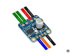
- DRV8871 motor driver module
- External power supply (12V)
- Breadboard and jumper wires
Circuit Diagram
To control the motor speed and direction, the ESP32 generates PWM signals and logic-level signals, which are sent to the DRV8871 motor driver. The motor driver regulates the power delivered to the motor and handles direction control based on the input signals.
DRV8871 Motor Driver Specifications:
- 6.5V to 45V motor power voltage
- Up to 5.5V logic level on IN pins
- 565mΩ Typical RDS(on) (high + low)
- 3.6A peak current
- PWM control
- Current limiting/regulation without an inline sense resistor
- Undervoltage lockout
- Overcurrent protection
- Thermal shutdown
Datasheet: Adafruit DRV8871 Brushed DC Motor Driver Breakout
Connections
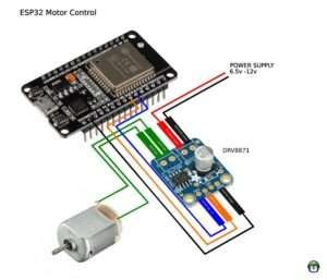
- Connect the motor’s positive and negative terminals to the motor driver’s output terminals (OUT1 and OUT2).
- VM Not connected (controller is powered by the motor power source)
- Connect the motor driver’s GND pin to the ESP32’s GND.
- Connect the motor driver’s IN1 pin to an ESP32 GPIO pin (e.g., GPIO 18) for direction control.
- Connect the motor driver’s IN2 pin to another ESP32 GPIO pin (e.g., GPIO 19) for direction control.
· · ─ ·𖥸· ─ · ·
Writing the MicroPython Code
Below is the sample MicroPython code for controlling the motor speed and direction:
from machine import Pin, PWM
from utime import sleep

in2 = PWM(Pin(18))     # Speed
in1 = Pin(19, Pin.OUT)  # Direction

in2.freq(500)         # set frequency. 1000 is default

while True:
    # Forward
    # in2:  1023 <-- Slower - Faster --> 0
    in1.on()
    print("Forward")
    in2.duty(0)  # Fast
    sleep(1)
    in2.duty(100)  # Slow
    sleep(1)
    in2.duty(200)  # Slower
    sleep(1)
    in2.duty(300)  # Slower x 2
    sleep(1)
    in2.duty(1023)  # stop
    sleep(1)

    # Reverse
    # in2:  0 <-- Slower - Faster --> 1023
    in1.off()
    print("Reverse")
    in2.duty(900)  # Fast
    sleep(1)
    in2.duty(600)    # Slow
    sleep(1)
    in2.duty(300)    # Slower
    sleep(1)
    in2.duty(0)     # Stopped
    sleep(1)
Like what you’re reading?
Help keep DevDigest
free and caffeine-powered
—buy me a coffee on Ko-fi.
PWM Frequency & Duty Cycle: Why It Matters
Understanding PWM isn’t just typing frequency = 5 kHz—it’s knowing why. Here’s what beginners should grasp:
1. Frequency influences torque & noise
- Low frequencies (e.g., 500 Hz) create louder, choppy motors due to audible clicking.
- Too high (e.g., >20 kHz), and some motor drivers falter or produce EMI.
2. Duty cycle directly controls motor behaviour
- 0% = motor off, 50% ≈ half speed, 100% = full speed.
- In heavy-load situations, even a high-duty signal may stall the motor due to insufficient torque.
3. Practical tuning steps
- Start at 1–5 kHz, with 50% duty to test smoothness.
- Observe motor noise and responsiveness. Adjust frequency in ±1 kHz steps.
- If torque feels weak at a nominal duty, raise the duty before increasing frequency.
Quick test snippet (MicroPython):
pwm.freq(2000)   # start at 2 kHz
for dc in range(0, 1024, 128):
    pwm.duty(dc)
    print(f"Duty: {dc/1023:.2%}")
    sleep_ms(1000)
Log how the motor responds at each step—learn your hardware’s sweet spot.
· · ─ ·𖥸· ─ · ·
Power, Safety & Noise: Protecting Your Build
DIY motor control on a budget is great—but without protection, it can burn your hardware faster than you blink.
1. Use a flyback diode (freewheeling diode):
In the guide’s DRV8871 hookup, ensure the motor’s power supply reverse-spikes are clamped. Most drivers already include this, but always double-check in your datasheet.
2. Watch thermal load and current draw:
- Use a multimeter to measure stall current during motor startup—it should stay within the DRV8871’s specs.
- If current peaks during pulsed operation, add a small electrolytic capacitor (>100 µF) across the supply to buffer power.
3. Don’t ignore cable management & grounding:
- Keep power and signal wires separated to reduce EMI.
- Use a shared ground between ESP32 and motor driver to prevent drifting voltage references and erratic behavior.
Why it matters:
A mismanaged power spike not only disrupts your PWM precision—MicroPython might freeze or reboot the ESP32. Protecting your hardware keeps your projects functional and durable, especially for community-driven or educational deployments.
· · ─ ·𖥸· ─ · ·
Real Control, Real Impact
FOSS Means Fewer Gatekeepers, More Possibility
In the world of microcontrollers, precision isn’t a luxury—it’s the difference between a working project and a burnt-out component. Learning how to properly implement ESP32 PWM motor control doesn’t just help your robot move or your smart system stay responsive—it empowers you to build smarter, with fewer dependencies and more resilience.
We didn’t just toggle a GPIO pin—we took control of a tool, demystified its behavior, and used it in a way that aligns with FOSS values: accessible, replicable, and rooted in real needs.
If this guide saved you time, stress, or money—or if you believe open tools should come with open wisdom—let’s keep the signal strong.
👉 Subscribe to the newsletter for more no-fluff tutorials, ethical hacking tips, and hands-on hardware lessons for real people solving real problems. Let’s build systems that serve everyone.
Like what you’re reading?
Help keep DevDigest
free and caffeine-powered
—buy me a coffee on Ko-fi.
Leave a Reply